| Hydronic Balance |
| The actuator can be pre-set to limit the working range of the valve which limits the maximum flow rate through the valve. Consequently, hydronic balance is achieved automatically without the use of additional balancing valves. |
| Control Signals |
The control signals, i.e. input signals and feedback automatically adapt to the pre-set working range of the valve. This means the maximum signal is equal to the maximum pre-set design flow limit. The digital control system is allowed to work throughout the full range of the signal independent of the working range. The valve can be programmed to operate in either the NC-normally closed mode so that it opens with an increasing signal or NO-normally open mode so that it closes with an increasing signal.
|
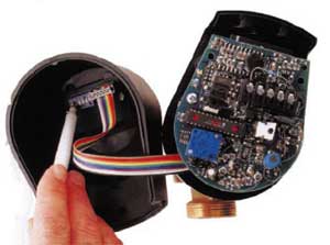
| Pre-setting the Maximum Flow Rate |
| The valve is adjusted to a maximum flow rate limit by setting the 6 dip switches located inside the top cover of the actuator. The switches are numbered 1 through 6 and can be set to the on or off position. The code combinations to produce each of the 51 possible flow rate maximums per valve are listed in the flow rate tables. |
 |
|
|
|