| Adjustment |
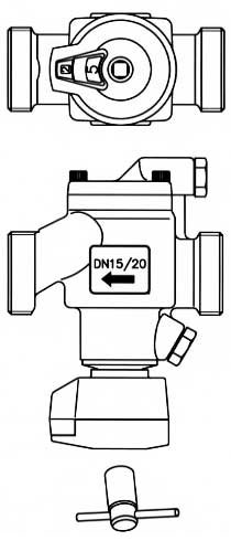
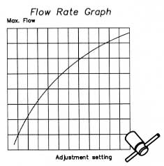
The internal mechanism is adjusted by an operation key which also turns the display mechanism. The numeric display shows two scales; one black reflecting full turns numbered 1-6, and one red reflecting tenths of full turns reflects the flow rate selected and can be read on setting/flow rate graph.
After the flow rate is set, the valve automatically registers the system pressure conditions and adjusts its orifice area to limit the flow rate to the selected maximum. As pressure conditions change, the valve will automatically re-adjust to maintain the selected flow rate. This eliminates the need to exactly know the distribution of pressure within a system.
Because of this dynamic reacting feature, one or more of the valves in the system can be re-adjusted without upsetting the other circuits.
The flow rate through the valve can be verified by reading the pressure differential across a pre-set valve opening. The pressure test ports can be supplied with optional pressure/temperature fittings for connecting conventional mechanical gauges or electronic sensors. |
 |
 |
|
|
|
|
|