| 1. |
The Standard Flow Cartridge |
|
This is our most popular cartridge. It is a single flow, 100% stainless steel cartridge. Its construction is shown in the cut-away photograph below, as Figure 1.
 |
|
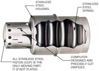
Figure. 1 CARTRIDGE CONSTRUCTION
|
It consists of a hollow piston (also referred to as cup) inside a housing. The piston has several ports (orifices) of various shapes and sizes that are designed by computer and cut very precisely. It has a unique noise reduction feature; the ports are divided into segments to eliminate the gushing noise of water flowing through a single large port.
The piston moves inside a housing against a spring and is the only moving part. Foe every flow rate, there is a unique combination of port shapes and sizes.
The operation of the cartridge is illustrated in Figure 2.
The function of the cartridge is to keep flow constant, while absorbing the dynamic pressure fluctuations in the system, within its differential pressure control range. |
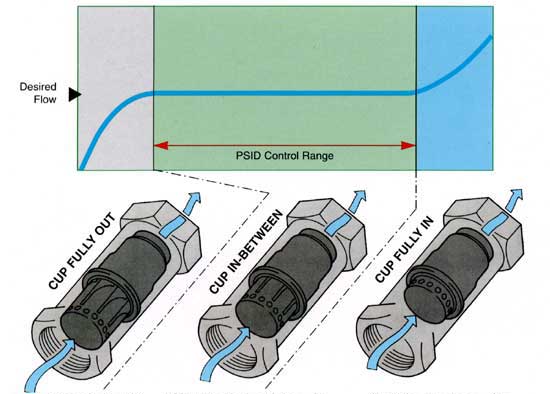 |
| Below the control range, the cartridge acts as a variable flow device allowing flow to vary below the rated amount. |
Within the wide control range, the cartridge modulates in response to pressure differential changes to maintain a fixed flow rate within ±5%accuracy. |
Above the control range, the cartridge acts as a variable flow device allowing flow to vary above
the rated amount. |
| Figure. 2 CARTRIDGE OPERATION |
|
|
Mathematically in the flow equation,

where
- Q =Flow (L/S)
- Cv =Cartridge flow coefficient (dependent on the orifice area)
 P =Differential Pressure (KPaD) across the cartridge. P =Differential Pressure (KPaD) across the cartridge.
the Cv is varied precisely in reaction to dynamic changes in P, to keep the flow constant.
Since the FlowCon control ranges are quite wide,you don't have to be very accurate in calculating the pressure drop; just verify that the differential pressure will stay within the control range you select.
If (very unlikely), the differential pressure across the cartridge falls below its control range (gray colored area in Figure 2.), the cup will come all the way out, exposing the maximum orifice area. Similarly (equally unlikely), if the differential pressure across the cartridge rises above its control range (blue colored area in Figure 2.), the cup will move all the way in, exposing the minimum orifice area. In both cases, the cartridge will now act as a fixed orifice device, varying flow based on the out-of-range differential pressure.
You do not have to worry about the cartridge ever shutting off the flow completely because a minimum orifice area is always open. |
|
|
|
|
|